Gyro PCB.
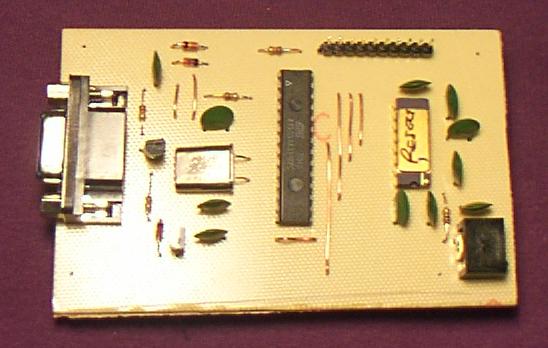 This is it. You can see it doesn't take much to make them work. The gyro is
the 16-pin DIP on the right. The big DIP in the middle is the Atmel AVR4433,
and the discretes scattered around the left are the RS-232 interface (well,
not true RS-232, but close enough for any PC I've worked with). The header
at the top is my connection for in-circuit programming of the AVR. It runs
on +5v; that's the power connector in the lower right corner.
This is it. You can see it doesn't take much to make them work. The gyro is
the 16-pin DIP on the right. The big DIP in the middle is the Atmel AVR4433,
and the discretes scattered around the left are the RS-232 interface (well,
not true RS-232, but close enough for any PC I've worked with). The header
at the top is my connection for in-circuit programming of the AVR. It runs
on +5v; that's the power connector in the lower right corner.
 home
home
© 2002 Joseph Rothweiler
Last modified $Date: 2002/09/06 21:27:47 $