Chris R. Brown's physics and astronomy stuff
280 MHz Radio Interferometer
Chris R. Brown's physics and astronomy stuff 280 MHz Radio Interferometer |
|||||
|
|
||||||||||||||
|
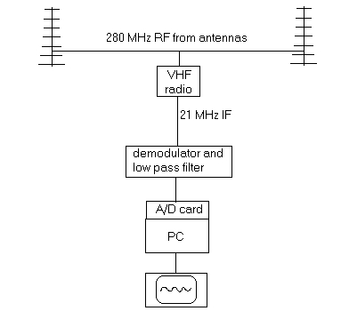
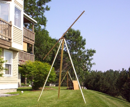
Radio Interferometer detects sun! Chris R. Brown July 2006 Well, I finally did it, after about 10 years of procrastinating. I built a pair of Yagis cut for 280 MHz, and T'd them
together at my receiver's RF input jack. The organization of all the stuff is shown in figure 1. The reciever, an old Watkins-Johnson
906A, has a bandwidth of 300 KHz.
The antennas, each with a half power beamwidth of about 50 degrees, were separated by 20 meters on a line running NW to
SE (dictated by convenience) and data was collected for two hours in mid-afternoon.
The VHF receiver was outside, sheltered from the sun halfway between the antennas. The 21 MHz IF signal was sent inside
to a noisy computer about 30 meters from the reciever. First results are shown below.
For this first effort, there was no attempt to reduce noise. The demodulator and low pass filter had been used for radio
meteor work, with a time constant of about 0.1 seconds, and I left it unchanged just to see what the noise spectrum looks
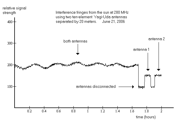
like. The A/D took a sample of the demodulator voltage every five seconds during the two hour observation. The presence of the sine wave pattern in Figure 3. is the icing on the cake. It is an unambiguous indicator of a radio
source in the sky, presumably the sun. At about 100,000 Janskys, there's not another likely candidate. (1 Jansky = 10E-26
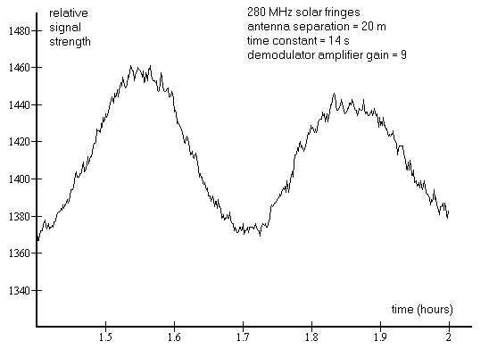
W/m^2 Hz) Subsequently, I increased the time constant to 14 seconds, still sampling once every five seconds, and added an op amp,
with gain of about 9. A portion of a solar observation is shown in figure 4. below. There are interesting periodic signals
riding on the sun's signal, aircraft perhaps, or satellites.
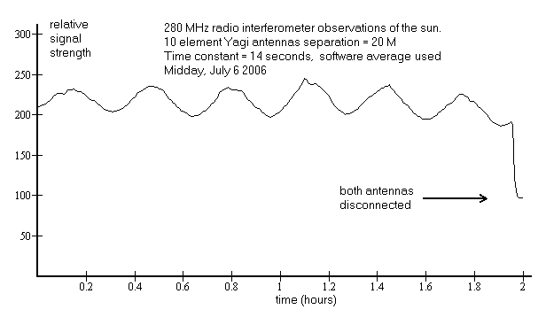
To further improve the signal to noise ratio in anticipation of a search for other radio sources, I added some software
averaging to the 14 s time constant in the low pass filter. Specifically, I sampled once per second, and saved the average
of these samples every thirty seconds. The op amp (or its supply) caused some drift, so I removed it in favor of passive components
in the demodulator and low pass filter. The signal for the sun with this arrangement is shown below.
I'm not certain that the increased sensitivity is sufficient to detect much less powerful radio sources than the sun. In
summer, CAS A and CYG A are not well placed for observation from my site. When the seasons change, or when I find a better
site, I'll press on. Also needed is better electronics between the antennas and the computer. Any suggestions would be welcome.
The software that operates the A/D card and saves the data is a homebrew in BASIC. The Yagi design program was inspired
by Guenter Hoch's design in Ch. 9 of the ARRL UHF/ microwave experimenter's handbook. Both of these programs are available
(for free of course) upon request. |
||||||||||||||
|
|
||||||||||||||