Chris R. Brown's physics and astronomy stuff
Photographing diffraction and interference effects
Chris R. Brown's physics and astronomy stuff Photographing diffraction and interference effects
|
|||||
|
|
||||
|
Introduction Here are some photos of diffraction and interference phenomenae. When I was a student, some of these photos showed up in the physics texts and I always wondered if it was difficult to get these pictures. So, now that I have some time, I decided to see if it is hard to get them or not. Actually, it is easy, if you know some tricks. I'll talk about these tricks, and show some photos and a setup. Then you and your motivated students can easily do it too. Setup All of these photos were taken with a simple, inexpensive arrangement that conveniently fit in a darkened basement, with about 6 meters between the light source and the camera. Several tables of the same height make this work convenient.
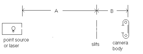
Figure 1. Setup for photographing diffraction patterns. The camera lens is removed, so that light from slits or other barriers falls directly on the film plane.
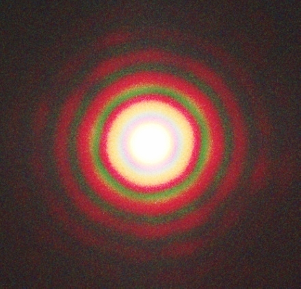
The dimensions A and B vary with the experiment, but a good starting point is A ~ 5 m and B ~ 0.5 m. When experimenting with setups, it is good to look at what will be photographed by using a telescope eyepiece. A standard 25 mm focal length Kelner or Plossl is fine for the purpose, as what is seen through the eyepiece is roughly what will show up on a 35 mm camera film plane. Figure 2. shows the diffraction and interference of coherent white light after striking a pinhole. This figure shows the bright central region, surrounded by colored rings. The shorter wavelengths, green in this exposure, show up first as you go from the central region outward. The film used here was sensitive to green an red, and to a lesser extent, blue, but does not accurately reproduce the pretty colors that you see when you look with your eye at the diffraction patterns using a telescope eyepiece.
Figure 2. Fringes from a pinhole in white light.
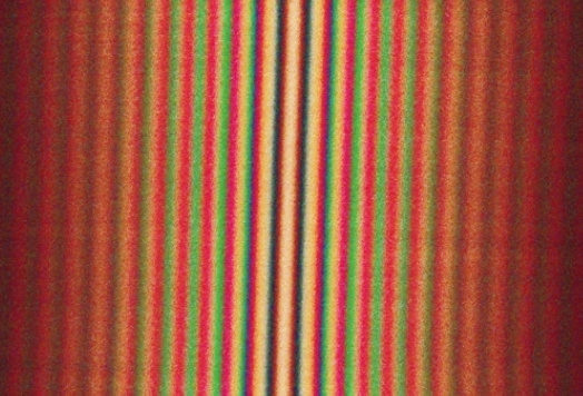
Making pinholes and slits To get good patterns from pinholes, the holes have to be as round as you can make them. In figure 2, some of the rings are not equally bright all around, and that is because my pinhole wasn't perfect. But it's not bad. Certainly ok for starters. To make pinholes, I cut some 3 cm squares from 0.3 mm thick soft aluminum roofing flashing. When cutting squares, a paper cutter does a nicer job than hand held scissors, which tend to warp the squares. Then I mounted a 1 mm diameter pin in a hand drill and with a few turns and some gentle pressure, started a hole. Then I took a 0.6 mm pin (a standard sewing pin)with a plastic sphere for a head, and carefully spun the pin in the hole from both sides of the square. This enlarges the hole slightly and most importantly, makes the hole round. Aluminum is very soft and after a little practice it takes only a few seconds to make good pinholes. The pinholes ranged in size from .3 to 1.0 mm. The pinholes or slits were then taped to a piece of stiff black paperboard about 10 cm by 15 cm and having a 2 cm hole in the center. This can be mounted in a variety of ways so that it doesn't move during the time when the film is being exposed. To make slits, I sprayed some flat black paint on a microscope slide. After the paint dried, I put a ruler across the slide and scored a slit with a razor blade, or two slits with two razor blades. The slit separation can be varied with shims of paper or metal foil. There are commercial suppliers of slits and pinholes too. Pasco Scientific is one source, there are many others. With slits and pinholes, it is possible to accurately measure diameters and separations by using a laser for illumination, and then measuring the patterns on a distant wall. Standard formulas then tell just how large the holes are, and how far apart the slits are. Below is figure 3. which shows the diffraction pattern of double slits in white light. The slits were separated by 0.5 mm. The central white band corresponds with zero path difference. Again, going away from the central line, the short wavelengths show up first. Each slit was very narrow, so that the convolution of the double slit pattern with the single slit pattern did not appear in this exposure.
Figure 3. Fringes from double slits in white light.
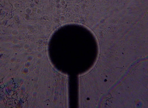
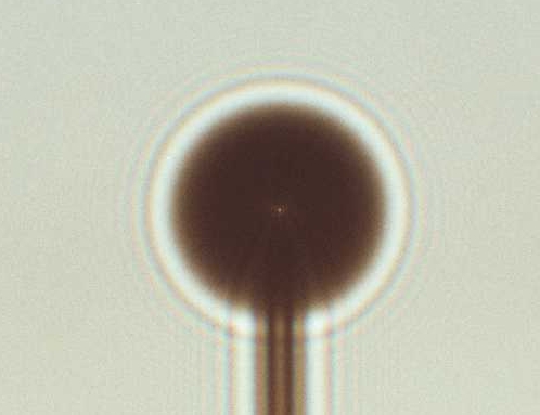
Light sources For a white light source, I have been using a 12 Volt, 2 Ampere automotive lamp with filaments that are about 3 mm in extent. From 5 m , the filament is small enough to provide sufficient coherence at the slits used in these photos. Initially, I used a 1 mm grain-of-wheat bulb, but the total light output was small, requiring long exposure times. The automotive bulb provided a good compromise between exposure times and coherence. A $10 red light laser pointer makes a wonderfully cheap light source. My pointer provides about 0.5 mW at 645 nm. ( I measured its wavelength by comparing its spectrum with a neon night light!) The beam should be spread out with a lens of about 5 cm focal length in order to get exposure times into the range covered by the camera. Cameras A 35 mm camera with a removable lens is economic at present, thought this is sure to change. Todays inexpensive digital cameras are not good because you can't remove the lens, the big secret for getting clean pictures. If you have any surface between the light sensitive layer and the pinhole or other barrier being photographed, imperfections and dust become diffraction sources, which produce spurious rings and other lens artifacts on the image. An example of this problem is shown in figure 6. This is compared to a no-lens photo of the same subject in figure 7. When SLR digital cameras have prices of a few hundred dollars, these comments will be obsolete. Because CCD chips are typically small, the spacing between the pinholes and the CCD plane will be reduced. Everything has to be smaller, including the pinholes. Ever try to make a 0.05 mm round hole? Also, taking the lens off a digital SLR camera for any period of time increases the risk of CCD surface contamination. Go with film, while you still can! Film exposure considerations Bracketing exposure times is a necessity when getting started. I found that three shots, three exposure times apart was good. Using the laser and ASA 400 film, 1 s, 1/8 s, and 1/60 s would always catch what I was looking for. Most times, 1/8 s did it best, but not always. With my white light source, 1 s, 10 s and 50 s made an adaquate exposure spread.
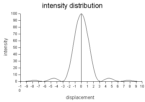
Figure 4. Intensity distribution of a single slit or a pinhole.
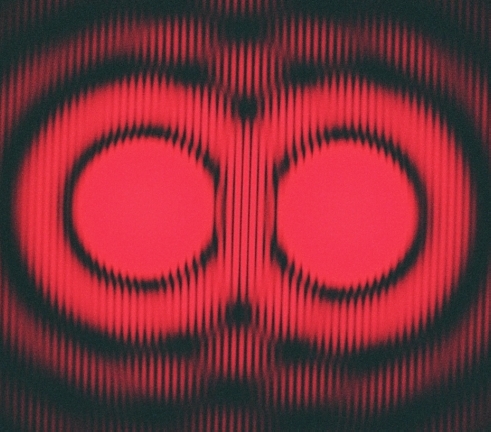
Some interesting physics Figure 4. is a sin x over x function, squared. It describes the brightness one expects from a single slit, or across the diameter of a pinhole diffraction pattern. What it doesn't show is the phase shift of 180 degrees that occurs in the light arriving at succesive rings around the central maximum. To see this in Figure 5., chose a ring to use for a phase reference, and inspect the interference fringe phase shifts as it passes through the rings of the pattern from the other hole.
Figure 5. Fringes from two pinholes at 645 nm. Adjacent rings alternate in phase.
Coherence Optics texts give formulas for the size of a lateral coherence region, which for these experiments should be 5 mm or so. A source a few millimeters in extent located 5 m or greater away from the slits or pinholes is adaquate.
Figure 6. Shadow of a 4 mm sphere in white light, using a digital camera with lens.
Figure 7. Shadow of a 4 mm sphere in white light, using a film camera with no lens. Note the spot in the center of the sphere. |
||||
|
|
||||